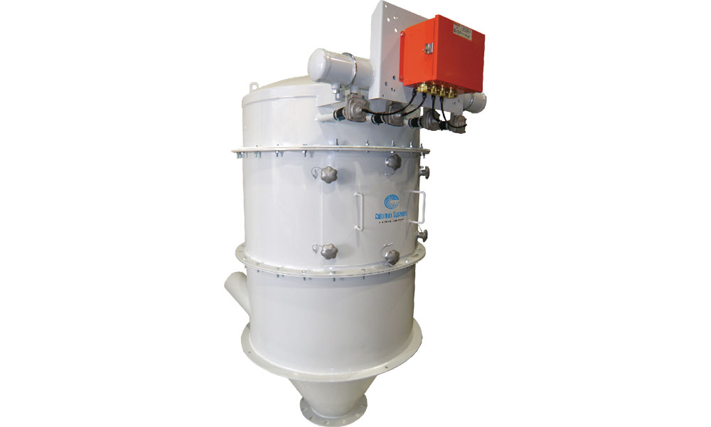
Filter Receiver
- Carbon steel construction, outside surfaces painted RAL7035 gray.
- Cleaning timer control panel with IP66 【NEMA4X] enclosure and 24 VDC operation.
- 454g polyester bags (includes cages) or 100% spun bond polyster catridge filters
- Pressure differential indicator
- No-tool access door
- ATEX 3GD
- CE compliant
- 1.4301(AISI 304) or 1.4404(AISI 316) stainless steel construction
- Hopper with safety grid and flanged adapter stubs
- Discharge arrangements, flow aids and accessories
- PTFE exterior membrane-coated cartridges or filter bags
- Oversized accumulator
- Explosion-proof NEMA 7 or 9 construction
- Explosion venting or suppression
- Support stand and service platform
- NEC Hazardous Location
- Bags and Cartridges with Grounding Strap
Application
Colormax Systems Filter Receiver provides automatic material-from-air separation. The tangential inlet located in the receiver’s circular hopper provides a cyclonic separation of the material from the air stream. Remaining airborne material is trapped by the filter element. Sequentially timed bursts of compressed air, controlled by solenoid valves, pulse the bags or cartridges and dislodge the dust particles to clean the filters. The filter element is protected from the material mainstream by a deflector shield. Efficient performance of the filter receiver is achieved through the proper selection of filter media and the correct air-to-cloth ratio, along with can velocity considerations.
Design
Standard material of construction is carbon steel with enamel coating. The unit’s filter element is cleaned by reverse jet cleaning from a compressed air accumulator. The air is directed through venturis, inducing a greater volume of air to clean the filter element for more complete dust particle dislodging. Only a single row of the filter element is pulsed at a time, leaving the remaining filter elements on-line. The interval between pulsing is adjustable to ensure optimal filter element cleaning. The receiver’s filter element is easily accessed for service through the quick access door. The access door is designed with a curved profile to minimize internal ledges. The air pulse cleaning of the filter element is regulated by the timer control panel. The timer allows easy adjustment of the frequency and duration of each pulse and a display shows which element row is currently being cleaned. All solenoids for pulse cleaning are located in the panel. Each receiver is equipped with a pressure differential indicator. The gauge measures the difference in pressure between the filter element housing and the clean air plenum, informing the operator of the effectiveness of the filter cleaning system.